In the world of RF passive components—such as couplers, attenuators, splitters, and terminators—RF connectors play a crucial role in ensuring signal integrity, mechanical reliability, and ease of integration. Choosing the right connector is essential for system performance, especially in 4G/5G base stations, DAS (Distributed Antenna Systems), and other high-frequency communication systems.

Below, we explore the most commonly used RF connector types in passive devices and their practical applications.


1. 7/16 DIN Connector

  • Frequency range: Up to 7.5 GHz

  • Impedance: 50 ohm

  • Features: Rugged, weatherproof, and low intermodulation (PIM)

  • Applications: Widely used in outdoor base stations, high-power RF systems, and feeder lines.

Why it’s common: The 7/16 DIN is known for its durability and stable performance in harsh outdoor environments. Its screw-type design ensures reliable mating.


2. N-Type Connector

  • Frequency range: DC to 11 GHz

  • Impedance: 50 ohm

  • Applications: Indoor/outdoor RF systems, antennas, repeaters, and test setups.

Strength: It offers a good balance between size, performance, and cost. Often seen in indoor RF networks and lower-power outdoor setups.


3. 4.3-10 Connector

  • Frequency range: Up to 12 GHz

  • Impedance: 50 ohm

  • Advantages: Compact size, lower PIM, and lightweight

  • Usage: Replacing 7/16 DIN in modern telecom setups, especially 5G deployments.

Note: The 4.3-10 comes in push-pull, hand-screw, and threaded types, giving flexibility in installation and maintenance.


4. SMA Connector

  • Frequency range: Up to 18 GHz (standard), 26 GHz (precision)

  • Impedance: 50 ohm

  • Usage: Lab test setups, IoT devices, low-power RF modules.

Why it’s used: Its compact design and wide frequency support make SMA ideal for indoor test equipment and high-frequency signal routing.


5. BNC Connector

  • Frequency range: Up to 4 GHz (depending on type)

  • Impedance: 50 or 75 ohm

  • Application: Test equipment, video systems, low-frequency RF signal routing.

Note: Quick connect/disconnect feature makes it convenient for lab environments.


Choosing the Right Connector for Your RF Passive Device

The choice of connector depends on factors like:

  • Frequency range of your system

  • Power level requirements

  • Environmental exposure (indoor vs. outdoor)

  • PIM sensitivity for 4G/5G networks

  • Mechanical durability and ease of installation

For modern communication systems—especially in 5G, IoT, and satellite applications—low-PIM and high-frequency support are becoming increasingly important in connector selection.
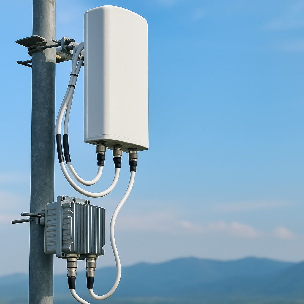
What Is a VHF Antenna?

VHF antennas operate within the Very High Frequency range of 30 MHz to 300 MHz. These antennas are commonly used in:

  • FM radio broadcasting (88–108 MHz)

  • Marine radio communication (156–174 MHz)

  • Aviation communication systems

  • Emergency and amateur radio operations

Due to their longer wavelengths, VHF antennas perform well in open and rural environments where line-of-sight coverage is available. However, they tend to be more affected by obstructions like buildings and terrain.


What Is a UHF Antenna?

In contrast, UHF antennas function within the Ultra High Frequency spectrum, ranging from 300 MHz to 3 GHz. Typical applications include:

  • Walkie-talkies and handheld radios (400–470 MHz)

  • Digital TV broadcasting

  • Wireless microphones and surveillance systems

  • RFID, Bluetooth, and Wi-Fi devices

Because UHF signals have shorter wavelengths, these antennas offer stronger signal penetration in dense urban or indoor environments, making them ideal for city-based communication systems.


UHF vs. VHF Antenna: Key Differences at a Glance

Feature VHF Antenna UHF Antenna
Frequency Range 30 MHz – 300 MHz 300 MHz – 3 GHz
Wavelength Longer Shorter
Signal Reach Better over long distances Better through buildings and obstacles
Penetration Ability Moderate High
Common Use Cases Marine, aviation, outdoor radio Indoor, urban, TV, RFID, handheld radios
Antenna Size Generally longer More compact

When to Choose VHF vs. UHF Antennas

Choose a VHF antenna if:

  • Your application is in open, rural, or maritime areas

  • You require longer communication range without much interference

  • You're working with FM or aviation bands

Choose a UHF antenna if:

  • Your setup is in an urban or indoor environment

  • You need better signal penetration through walls and buildings

  • You're using Wi-Fi, surveillance systems, or mobile communication devices


Why the Difference Between UHF and VHF Antenna Matters

Selecting the wrong antenna type can result in signal loss, coverage gaps, or regulatory issues. For instance, using a UHF antenna in open water may cause weak signal performance, while VHF antennas in a skyscraper may suffer from reflection and obstruction.

When sourcing antennas, it's also essential to consider:

  • Antenna gain (dBi)

  • Mounting requirements

  • Environmental durability (IP rating)

  • Frequency tuning or bandwidth range

What Is an RF Filter?

An RF filter is a passive or active component that allows signals within a certain frequency range to pass while attenuating signals outside that range. Filters are essential in both transmit and receive chains to isolate specific frequencies and prevent crosstalk, interference, or signal distortion.

Types of Filters by Frequency Selection

Depending on the application, filters come in various types:

1. Low-Pass Filter (LPF)

  • Allows frequencies below a cutoff frequency to pass

  • Blocks higher frequencies

  • Used to eliminate high-frequency noise in receivers

2. High-Pass Filter (HPF)

  • Allows high frequencies to pass

  • Blocks signals below a cutoff frequency

  • Common in antenna feed networks to isolate uplink signals

3. Band-Pass Filter (BPF)

  • Passes signals within a defined frequency band

  • Rejects all others

  • Widely used in 4G/5G systems to isolate specific communication bands (e.g., 3.5 GHz, 2.4 GHz)

4. Band-Stop Filter (Notch Filter)

  • Blocks a narrow band of frequencies

  • Passes others

  • Used for interference suppression or EMI mitigation


How Do Filters Actually Work?

Filters operate based on the principles of resonance, impedance matching, and signal phase control. They are usually built from combinations of:

  • Inductors (L) – Impede high-frequency signals

  • Capacitors (C) – Block low-frequency signals

  • Resonant cavities or dielectric resonators – In cavity filters

By arranging these components in specific topologies (π-type, T-type, LC ladder, etc.), engineers can tailor the filter's frequency response curve — that is, how the signal amplitude changes with frequency.

In cavity filters, for instance, signal energy resonates within a metal cavity tuned to a particular band, creating very steep roll-off and excellent rejection outside the band.


Applications of RF Filters

Filters are used wherever frequency control is essential:

  • Base stations (macro and small cell) – Clean transmission and reception bands

  • Satellite and aerospace – Avoid overlap between communication and telemetry channels

  • IoT devices and routers – Isolate Wi-Fi and LTE signals

  • Test and measurement equipment – Prevent out-of-band noise during analysis


Key Parameters When Selecting a Filter

To choose the right filter, consider:

Parameter Meaning
Center Frequency The midpoint of the passband
Bandwidth The range of frequencies the filter allows
Insertion Loss Signal loss within the passband (lower is better)
Return Loss Indicates how well the filter matches impedance
Rejection Attenuation level outside the passband
Power Handling How much RF power the filter can tolerate

Passive vs. Active Filters

  • Passive Filters use only capacitors, inductors, and resistors.

    • No external power needed

    • Simpler and more reliable

  • Active Filters include amplifiers (usually op-amps)

    • Can boost signal, but require power and add complexity

    • Rare in high-frequency RF systems

To test the power of a load, you can follow these steps:

  1. Gather Equipment: You'll need a multimeter, wattmeter, or power analyzer, depending on the accuracy required.

  2. Connect the Load: Ensure the load (such as a resistor, motor, or appliance) is properly connected to the power source.

  3. Measure Voltage: Use the multimeter to measure the voltage across the load. Make sure to set the multimeter to the correct voltage setting.

  4. Measure Current: Measure the current flowing through the load using the multimeter. If using a clamp meter, clamp it around one of the wires.

  5. Calculate Power: Use the formula:

    Power (P)=Voltage (V)×Current (I)\text{Power (P)} = \text{Voltage (V)} \times \text{Current (I)}

    for DC circuits, or for AC circuits, consider the power factor:

    Power (P)=Voltage (V)×Current (I)×Power Factor (PF)\text{Power (P)} = \text{Voltage (V)} \times \text{Current (I)} \times \text{Power Factor (PF)}
  6. Record Results: Document your measurements and calculations for reference.

  7. Safety Precautions: Always follow safety guidelines to prevent electrical hazards.

These steps will help you accurately assess the power consumption of a termination load.

1. Introduction: The Role of Passive Components in DAS

Distributed Antenna Systems (DAS) play a vital role in enhancing wireless coverage in complex environments like airports, stadiums, hospitals, and office buildings. While active equipment such as base stations and repeaters often receive the most attention, passive components—such as power splitters, directional couplers, loads, tappers, and hybrid combiners—are essential for signal distribution and optimization within DAS infrastructure.

Their design and performance directly influence system efficiency, PIM (Passive Intermodulation) behavior, and long-term reliability.


2. Key Performance Metrics for Passive Components in DAS

When evaluating or selecting passive RF components for DAS, engineers must consider multiple performance parameters beyond just insertion loss. These include:

  • Low PIM Levels (e.g., < –150 dBc):
    Critical for high-capacity systems, particularly those supporting LTE and 5G NR. Poor PIM performance can lead to intermodulation distortion that degrades signal quality.

  • Broad Frequency Range (e.g., 698–2700 MHz / 698–3800 MHz):
    Ensures compatibility with multi-band and multi-operator systems, avoiding the need for multiple component sets.

  • VSWR and Return Loss:
    Poor impedance matching can cause signal reflection, leading to reduced efficiency and increased power loss.

  • Power Handling Capability:
    Components must support both uplink and downlink power levels, especially in high-gain DAS topologies.


3. Common Passive Devices in DAS and How to Optimize Them

Power Splitters

Power splitters divide input signals into multiple outputs with equal or specific ratios. For optimal performance:

  • Use low insertion loss designs to reduce signal degradation.

  • Ensure phase balance across outputs to maintain signal integrity.

  • Choose products with robust mechanical design and N-type or 4.3-10 connectors to ensure low PIM.

Directional Couplers

Directional couplers are used to tap off small amounts of signal for monitoring or feedback purposes.
To improve performance:

  • Select units with tight coupling accuracy and excellent directivity.

  • Ensure broadband support for DAS systems operating across wide frequency bands.

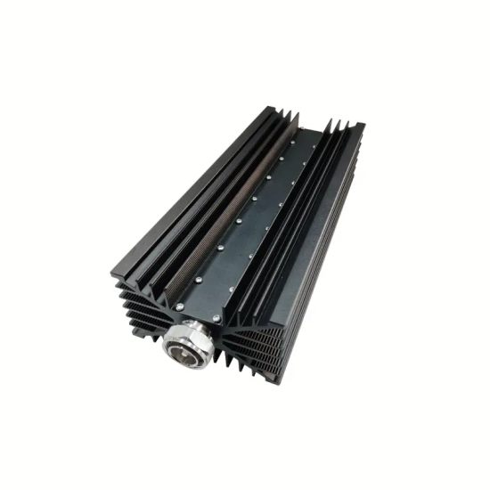
RF Loads and Terminations

Used to terminate unused ports without reflection:

  • Choose high-power, low-VSWR loads to safely dissipate RF energy.

  • Always confirm connector compatibility and thermal reliability.


4. Installation Considerations That Affect Performance

Even the highest-spec passive component can underperform if improperly installed. Key practices include:

  • Avoid tight bends or improper cable grounding that introduce unwanted reflections.

  • Maintain consistent torque across all connectors to prevent PIM spikes.

  • Keep all passive components clean and dry; contaminants can severely affect PIM.


5. Emerging Trends: 5G-Ready Passive Components

With the increasing deployment of 5G DAS, passive components must now accommodate frequencies up to 3.8 GHz and support Massive MIMO or beamforming-compatible architecture.

Look for:

  • Ultra-wideband combiners and hybrid couplers

  • Low-profile, panel-mount components for space-constrained indoor applications

  • Modular PIM testable units that allow on-site verification

The RF industry is experiencing rapid growth as new technologies and applications reshape the market. With the global demand for faster, more reliable wireless communication, RF components have become more critical than ever.


5G and Beyond


The global rollout of 5G networks has significantly boosted the demand for RF components such as power splitters, couplers, and antennas. In addition, research and development in 6G and millimeter-wave communication are pushing RF designs to higher frequencies and stricter performance standards. These advancements require components with low PIM, higher power handling, and superior reliability.


Emerging Applications


RF sensing technologies are being adopted in smart homes, healthcare, and industrial automation. By leveraging RF signals to detect motion, monitor health parameters, or enhance security, RF devices are expanding beyond traditional communication uses. This is creating new opportunities for companies specializing in antennas, filters, and RF modules.


AI and Design Automation


Another notable trend is the integration of AI in RF design and testing. AI-powered tools allow faster optimization of circuits and antennas, reducing time-to-market while improving performance. This is especially relevant for high-frequency components where traditional design processes can be time-consuming.


As industries like IoT, autonomous vehicles, and satellite communications continue to evolve, the RF market will maintain strong momentum. Companies with expertise in RF components and custom solutions are well-positioned to meet these growing needs.


At Maniron, with over 20 years of experience in RF component manufacturing, we are committed to delivering high-quality products and innovative solutions that empower modern wireless technologies.

In the fast-evolving communication industry, Public Safety Distributed Antenna Systems (DAS) play a critical role in ensuring reliable coverage for emergency responders and critical infrastructure. These systems rely on advanced RF components to optimize signal distribution. Three key elements—Yagi Antenna, Power Divider, and Directional Coupler—are essential for their functionality.

1. Yagi Antenna: Directional Coverage for Critical Areas

A Yagi Antenna is a directional antenna designed for long-range signal transmission with high gain. In public safety DAS, it ensures focused coverage in tunnels, stadiums, or high-rise buildings where omnidirectional antennas may fail. Its compact design and adjustable beamwidth make it ideal for confined spaces.

2. Power Divider: Balanced Signal Distribution

A Power Divider splits input signals into multiple outputs with minimal loss. In DAS networks, it ensures balanced RF power distribution to multiple antennas, preventing signal degradation. This is crucial for maintaining uniform coverage in large venues or underground facilities.

3. Directional Coupler: Monitoring and Feedback

A Directional Coupler allows real-time signal monitoring by sampling a portion of the transmitted power without disrupting the main path. Public safety DAS uses it to detect signal strength and troubleshoot issues proactively, ensuring uninterrupted communication during emergencies.

Conclusion

The integration of Yagi Antennas, Power Dividers, and Directional Couplers enhances the reliability of public safety DAS, enabling seamless communication for first responders. As urban environments grow more complex, these components will remain indispensable in building resilient communication networks.

For more insights on DAS solutions, explore our latest case studies on www.manirontronics.com

What is PIM and Why "Low" PIM is Critical?


PIM stands for Passive Intermodulation, a form of signal distortion that occurs when two or more high-power RF signals mix within a passive component—such as connectors, cables, power splitters, couplers, or antennas—and create unwanted interference at new frequencies. These new frequencies can degrade system performance, reduce data throughput, and affect overall network quality, especially in multi-band and high-density environments.

Low PIM means that a component is specifically designed and manufactured to minimize intermodulation interference, often below –150 dBc or even –161 dBc. In mission-critical networks—such as public safety DAS, 5G base stations, and in-building wireless systems—Low PIM is not a feature. It's a requirement.


What Causes PIM?

PIM is typically caused by:

  • Poor mechanical contacts (e.g., loose or corroded connectors)

  • Ferromagnetic materials inside components

  • Microscopic gaps and inconsistent plating on conductor surfaces

  • Aging and wear from repeated installation/removal

That’s why high-performance passive components require precision engineering, non-ferrous materials, and strict quality control throughout production.


How Maniron Ensures Low PIM Performance

At Maniron, our Low PIM-rated RF passive components are designed and tested to meet or exceed industry standards, offering:

  • PIM rating as low as -161 dBc @ 2x20W (typical)

  • Robust mechanical design for stable and consistent performance

  • Silver or tri-metal plated connectors for long-term reliability

  • Independent factory PIM testing with full traceability

  • Low VSWR and insertion loss, ensuring overall signal integrity

Whether you need Low PIM 3dB hybrid couplers, termination loads, directional couplers, or power splitters, Maniron delivers products you can trust in real-world deployments.


Applications That Demand Low PIM

Low PIM components are essential in:

  • 5G and LTE base station deployments (macro and small cells)

  • In-building Distributed Antenna Systems (DAS)

  • Public safety and emergency networks

  • High-speed rail and tunnel coverage systems

  • Multi-operator or multi-band shared networks

In any environment where multiple RF signals coexist, PIM can be the invisible bottleneck. Using Low PIM components ensures your network performs as intended.


Directional couplers are widely used in RF systems for signal sampling, power monitoring, VSWR detection, and PIM testing. While these components are passive by nature, their performance is highly dependent on how each port is terminated—especially the coupled port.

In real-world applications, improper termination of the coupled port—either by leaving it open, using poorly matched devices, or low-quality cables—can severely affect the performance of the coupler and even compromise overall system accuracy.

In this article, we explore:
Which key performance indicators are affected when the coupled port of a directional coupler is mismatched—and why it matters.


1. Basic Structure of a Directional Coupler

A typical directional coupler has four ports:

  • Port 1 (Input): Where the main RF signal enters

  • Port 2 (Output): Where the main signal exits

  • Port 3 (Coupled): Taps a small portion of the forward signal

  • Port 4 (Isolated): Ideally outputs no signal; usually terminated with 50Ω

The coupled port (Port 3) provides a low-power replica of the mainline signal for measurement or feedback. However, if the port is not properly terminated, the reflected signal can travel back into the system and interfere with accurate signal extraction.


2. Common Coupled Port Mismatch Scenarios

Some frequent mistakes in field setups include:

  • Leaving the coupled port open

  • Connecting a device with poor impedance match

  • Using poor-quality connectors or test cables

All of the above can cause signal reflection at the coupled port, affecting system accuracy and introducing measurement errors.


3. What Performance Metrics Are Affected?

1. Coupling Level Deviation

The coupling value (e.g., 10 dB, 20 dB) is designed to be fixed. However, a mismatched coupled port can introduce reflection that disturbs the internal coupling path, causing unintended fluctuations in coupled power output.

Impact: Power monitoring becomes inaccurate, and feedback loops may malfunction.


2. Directivity Degradation

Directivity measures how well the coupler distinguishes forward from reverse signals. It is defined as:

Directivity (dB) = Coupling (forward) - Coupling (reverse)

A mismatch on the coupled port causes reflected signals to mix with reverse signals, lowering directivity. This makes it harder to differentiate between incident and reflected signals.

 Impact: Lower accuracy in reflection measurements, affecting VSWR or PIM analysis.


3. VSWR Increase

Although directional couplers are designed for low return loss, reflected waves from the mismatched coupled port can introduce internal standing waves and alter the overall match of the system.

Impact: Higher VSWR may reflect power back to amplifiers or test equipment, causing instability.


4. Insertion Loss Increase

Directional couplers are typically very low loss (e.g., <0.2 dB). However, internal reflections from the coupled port can slightly affect the mainline energy flow, increasing insertion loss.

Impact: System efficiency decreases; more power is lost in the passive path.


4. How to Avoid Coupled Port Mismatch Issues

To prevent degradation of coupler performance:

  • Always terminate the coupled port with a 50Ω load when not in use

  • Use low PIM, precision termination loads rated for the operating frequency and power

  • Avoid frequent connector plugging/unplugging

  • Clean connectors regularly and use high-quality RF cables

In RF and microwave communication systems, precise control over signal strength is critical. A coaxial variable attenuator is a key component used to adjust the amplitude of RF signals without distorting the waveform. Whether you're testing signal paths, protecting sensitive equipment, or balancing signal levels in a network, variable attenuators offer both flexibility and accuracy.

What Is a Coaxial Variable Attenuator?

A coaxial variable attenuator is a type of RF attenuator housed in a coaxial structure, designed to reduce the power of an RF signal dynamically. Unlike fixed attenuators, variable models allow users to manually or electronically adjust attenuation levels, typically measured in decibels (dB). These devices are crucial in RF labs, test setups, base station infrastructure, and satellite systems.

Key Features:

  • Adjustable Attenuation Range (e.g., 0–30 dB or 0–60 dB)

  • High-frequency compatibility (up to 18 GHz or more)

  • Low VSWR for minimal signal reflection

  • Precision tuning via dial or digital control

  • Durable coaxial connectors such as N-type, SMA, or BNC


Common Applications

1. Signal Testing and Calibration

Engineers use variable attenuators to calibrate RF signals during device testing. They help simulate signal loss conditions and ensure the DUT (Device Under Test) operates within specified limits.

2. Protecting Sensitive Equipment

By attenuating high-power signals, these devices protect RF receivers, analyzers, and amplifiers from overloading or damage.

3. Impedance Matching and Balancing

In complex RF systems like DAS (Distributed Antenna Systems) or repeater networks, coaxial variable attenuators help balance power levels and maintain optimal signal performance.

4. Base Station and Satellite Systems

They're essential in telecom infrastructure to fine-tune signal levels for both uplink and downlink channels.


Why Use a Coaxial Design?

The coaxial structure provides excellent shielding, mechanical stability, and compatibility with RF cables and connectors. This ensures minimal loss and reflection, critical in high-frequency applications.

Many of the variable attenuators offered by Luxun Electronic feature precision dials and high thermal stability, making them ideal for telecom operators and RF laboratories.


Factors to Consider When Choosing a Variable Attenuator

  • Frequency Range: Ensure it covers the operating bandwidth (e.g., 0–6 GHz or 2–18 GHz).

  • Maximum Input Power: Choose a model that can handle your signal strength.

  • Connector Type: Match with your existing RF cables (SMA, N-type, etc.).

  • Control Method: Manual vs. digitally controlled attenuation.

  • Linearity and Repeatability: Important for lab-grade measurements.